Go to Tashika top
Go to Tashika top Go to Tashika products
Go to Tashika top Go to Tashika top
Home > Products > Temperature Sensors, Instruments and Components > Temperature Monitoring Sytem
Title bar - products
Titile bar - Temperature sensors, instruments and components, products
RELAY LENS TYPE,
WINDOWS VERSION FURNANCE MONITORING SYSTEM

DESCRIPTION:
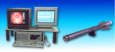
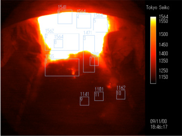
The furnace monitoring system measures two dimensional temperature pattern by using a CCD camera having its optical sensitivity in the near infrared region and the image processing unit having the facility of converting the thermal image to the temperature pattern.

A narrow relay lens of 77mm in outer diameter can be installed in a furnace wall through a small hole. Wide viewing inside the furnace can be obtained by virtue of the relay lens.

The temperature scale of the system is guaranteed as the JCSS grade.

The graphic software works on the Windows OS. The temperature trend data and the live temperature pattern are displayed on a CRT and a monitor each other. Attaching the optional unit to the image processing unit, the temperature trend data of 8 points and the alarm signals can be fed out to the peripheral unit. Both are useful for the plant operation.


Wide view angle assisted by relay lens


Multiple measurement of up to 11 points

UTILITIES
Average volumes of the utilities are shown below:

  • Cooling / Purge Air Quality
Oil and vapor free clean air of instrument Grade. Air containing oil or vapor will cause the lens contamination. Flow Rate 350-800 Nlit./min. (Regulated with furnace condition) Pressure 0.1-0.3MPa
  • Sealing Air
Flow Rate 100-150Nlit./min.; Pressure Approx. 0.1MPa
  • Cooling Water
Flow Rate 5-15lit./min. (for relay lens cooling) 3-10lit./min.
(for CCD camera cooling)Pressure 0.05-0.3MPa  
  • Power Supply
AC100V, 500VA  

OPERATION
Temperature Measurement

  • The temperature change of up to 11 areas and the temperature difference of up to 3 pairs among these areas can be measured. The measuring areas are assigned on the graphic screen by using the standard software.
  • Temperature changes of 11 areas are displayed on the trend graph and each values are displayed by the graph.
  • The position and the size of the measuring area can be assigned in the software.
  • Displaying temperature of each measuring area on the screen can be selected among the maximum, the minimum, or the average mode.
  • The emissivity and the offset temperature can be assigned to every measuring area independently.
  • 8 temperature data among 11 measuring areas can be fed out with the 4 20mA analog signal as the optional charge. 
Warning
  • The upper and the lower temperature limit assigned to each measuring area make it possible to display the warning temperature on the screen.
  • The system healthy signal and the upper or lower temperature limit signal can be fed out as the contact point signal (Optional charge)
Thermal image display(Pseudo color)
  • The thermal image obtained by the CCD camera is modified to the colored temperature pattern and displayed on the screen.
  • There are 4 color sets for the coloring of the temperature pattern. One of them is open to users for changing the color tone freely.
Data saving and Accessing
  • Temperature data of 11 measuring areas and the still thermal image can be stored on a hard disc.
  • Stored data can be accessed with the system software and displayed on the screen.
  • Filed data are arranged to the text mode and thermal images are arranged to the bitmap format. Both the data and the image on the hard disc can be accessed with commercial software.
Printing
  • A hard copy of the image on the screen can be obtained with customer's color printer.

GRAPHIC DISPLAY

Measuring data on the CRT

Thermal image on the monitor
Back to Top
For further information please Email us totashika e-mail addressmail
Home > Products > Temperature Sensors, Instruments and Components > Temperature Monitoring Sytem